|
Label:: |
RF
75-7-9/A |
RF
75-7-9/AU |
CATV
2.0/9.3A |
CATV
2.0/9.3 AU |
RF
75-7-9/C |
RF
75-7-9/CU |
CATV
2.0/9.3C |
CATV
2.0/9.3CU |
RF
75-9-09 |
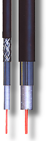
Construction |
Inner
conductor |
Solid copper
wire |
|
|
|
|
|
|
|
|
Diameter(mm),nom |
1.6 |
1.6 |
2.0 |
2.0 |
1.6 |
1.6 |
2.0 |
2.0 |
2.6 |
Isolation |
Foam. PE |
Diameter over isolation (mm), nom |
7.3 |
7.3 |
9.3 |
9.3 |
7.3 |
7.3 |
9.3 |
9.3 |
9.5 |
Outer
conducto |
Al tape |
Cu tape |
Thickness
of foil mm |
0.15 |
0.15 |
0.15 |
0.15 |
0.1 |
0.1 |
0.1 |
0.1 |
0.25 |
Add.
element |
- |
Suporting
strand |
- |
Suporting
strand |
- |
Suporting
strand |
- |
Suporting
strand |
2xFe
tape
0.1 mm |
Sheat |
PE |
PE |
PE |
PE |
PE |
PE |
PE |
PE |
Al
+ PE |
Overall diameter
(mm), nom |
10.5 |
10.5
x 17.6 |
12.8 |
22
x 12.8 |
10.5 |
17
x 10.5 |
12.8 |
21.5
x 12.8 |
16.0 |
| Electrical
characteristics |
| Characteristic impedance Ohm |
75+-3 |
75+-3 |
75+-2 |
75+-2 |
75+-3 |
75+-3 |
75+-2 |
75+-2 |
75+-1.5 |
| Loop resistance at 200C, (Ohm/km), max |
16.5 |
16.5 |
12.5 |
12.5 |
15 |
15 |
11 |
11 |
6 |
Capacitance,
nom. pF/m |
55 |
55 |
53 |
53 |
55 |
55 |
53 |
53 |
47 |
Return loss, min. |
30
- 450 Mhz * |
22 |
22 |
22 |
22 |
22 |
22 |
22 |
22 |
26 |
450
- 600 MHz ** |
20 |
20 |
20 |
20 |
20 |
20 |
20 |
20 |
26 |
Nominal attenuation at 200C (dB/100m) |
1
MHz |
0.4 |
0.4 |
0.3 |
0.3 |
0.4 |
0.4 |
0.3 |
0.3 |
0.24 |
15
MHz |
1.6 |
1.6 |
1.2 |
1.2 |
1.5 |
1.5 |
1.2 |
1.2 |
0.92 |
40
MHz |
2.6 |
2.6 |
2.0 |
2.0 |
2.4 |
2.4 |
1.8 |
1.8 |
1.50 |
100
MHz |
4.3 |
4.3 |
3.1 |
3.1 |
4.1 |
4.1 |
3.0 |
3.0 |
2.40 |
200
MHz *** |
6.0 |
6.0 |
4.7 |
4.7 |
6.0 |
6.0 |
4.6 |
4.6 |
3.40 |
270
MHz |
8.0 |
8.0 |
5.5 |
5.5 |
7.1 |
7.1 |
5.5 |
5.5 |
4.00 |
500
MHz |
11.2 |
11.2 |
8.3 |
8.3 |
10.1 |
10.1 |
8.3 |
8.3 |
5.50 |
960
MHz |
16.0 |
16.0 |
13.5 |
13.5 |
14.7 |
14.7 |
13.5 |
13.5 |
8.00 |
| Mechanical
characteristics |
| Permissible bending radius, (mm). min |
80 |
100 |
100 |
120 |
80 |
100 |
100 |
120 |
600 |
| Max. tensile force (N) |
400 |
1500 |
500 |
1500 |
400 |
1500 |
500 |
1500 |
300 |
| Total weigth.approx. kg/km |
95 |
160 |
125 |
230 |
110 |
165 |
143 |
245 |
300 |
| Delivery length (m) |
500,1000 |
500,1000 |
500,1000 |
500 |
500,1000 |
500,1000 |
500,1000 |
500 |
610 |
| Application |
| |
For internal assembly and underground laying |
For
aeriel assembly |
For
underground laying |
For
aeriel assembly |
For
internal assembly and underground laying |
For
aeriel assembly |
For
underground layin |
For
aeriel assembly |
For
underground layin |
* - It is permitted that 6 exceeded values can be less for 4 dB than
prescribed value.
** - It is permitted that 3 exceeded values can be less for 4 dB than prescribed
value .
*** - Attenuation at frequency from 200 MHz is given like nominal |
|
|