Cable
accessories
INDOOR CABLE TERMINAL BOX
KGTu 10
APPLICATION
Indoor cable terminal boxes are used for terminating three
core paper insulated cables, 10 kV (classical or "NON-DRAINING"). They are
produced in two variants: protection of cable cores with oil resistance heat-shrinkable
tubes or with heat-shrinkable tubes with inner adhesive layer.
CONSTRUCTION
Terminal box is made of glass, which has excellent
mechanical and electrical properties and enables control oil level. If required, oil can
be poured. Both the caps on the top and metal cone are made of tinned brass.
Heat-shrinkable tubes enable good sealing of cable terminal box. Conductor is connected
with cable lugs (copper or bimetal). Data for choice of indoor cable terminal box KGTu are
shown in the following table.
.
| Type |
Cross-section (mm2) |
Dimensions
of sector sections
h × b (mm) |
Diameter of opening in box (mm) |
| KGTu - 1 |
50 70 95 |
13,38 × 19,47
14,71 × 21,70
16,43 × 24,0 |
32 |
| KGTu - 2 |
120 150 185 |
17,39 × 26,35
18,69 × 29,04
20,03 × 31,13 |
45 |
| KGTu - 3 |
240 300 |
22,38 × 34,68
23,94 × 37,81 |
55 |
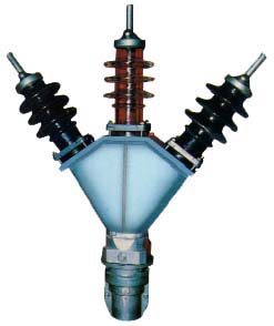
OUTDOOR CABLE TERMINAL BOX
KGTs 10
APPLICATION
Outdoor cable terminal boxes are used for terminating three core
paper insulated cables with copper or aluminium conductor cross-sections up to 240 mm2
and voltage up to 12 kV.
CONSTRUCTION
Terminal box KGTs 10 consists of:
- Box of aluminium alloy
- Three glass or porcelain isolators
- Tined copper or brass cone for sealing cable and terminal box.
Connection conductors and cable connectors can be carried out by soldering or
crimping. Terminal box is connected to overhead line conductors or other elements of power
construction with special connection clamps. After mounting, terminal box is filled with
oil compound. Total mass of terminal box without oil compound and connections elements is
approx.13kg..
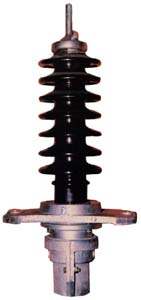
TERMINAL
BOX KGTsz 35 and KGJs 35
APPLICATION
Cable terminal box KGTsz 35 is used for terminating three core
power cables with paper insulation and lead sheath over each core cables, with copper or
aluminium conductors, 20-35 kV. Cable terminal box KGJsz is used for terminating single
core cables with paper insulation, with copper or aluminium conductors for voltages 20-35
kV.
CONSTRUCTION
Terminal Box consist of:
- Three glass or porcelain insulators
- Supporter for insulators
- Cable gland
- Dividing box
These terminal boxes are filled up with high voltage
"NON-DRAINING" oil compound. Both the caps on the top and metal cone are made of
tined brass. Connection of the cap to overhead line conductors or other elements of power
construction are made with screw clamps, insulated conductors or compression type terminal
lugs. The cable cores terminating is carried out by copper or aluminium- copper
connectors. These terminal box is proved according to VDE 0278 standard.
STRAIGHT THROUGH JOINTS BOXES
KS FOR POWER CABLES
APPLICATION
Straight through joint boxes type KS, according to JUS N.F4.031
standard, are applied for jointing the power cables with impregnated paper insulation:
- Straight through joint boxes type KS with lead sleeve for cables with common
metal coating, nominal voltage 1-10 kV(choice according to table 1);
- Straight through joint boxes type KS/H with lead sleeve for cables with common
metal coating, nominal voltage 15-35 kV (choice according to table 2);
- Straight through joint boxes type KS/HE with lead sleeves for cables with metal
coating over each core, nominal voltage 15-35 kV (choice according to table 3);
- Straight trough joints boxes type KS/P with lead sleeve for cables in various
constructions, one with common and other with separate metal coating over each core,
nominal voltage 20-35 kV (choice according to table 4);
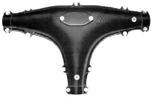
- Branch joints boxes type KSR with or without lead sleeve for in cases of
branching uncut and cut cables, nominal voltage 1-10 kV (choice according to table 5).
All protective boxes (outdoor protection) are made of cast iron
with cover, except special boxes KS up to 10 kV, which have protection of heat-shrinkable
tube. Protective boxes are filled up with bitumen compound and lead sleeves are filled up
with high voltage oil compound.
Table 1.
| Type of |
Lead |
Cross-section (mm2) |
Dimensions
ca. mm |
Weight
ca. kg |
| joint box |
sleeve |
single
core
1 kV |
two
cores
1 kV |
three
cores
1, 6 and
10 kV |
four cores
1-10 kV |
l1 (L) |
l2 |
l3 |
d1 |
d2 |
h |
b (D) |
Sleeve |
Filling
compo-und |
| KS 19 |
KSU 19 |
6-95 |
2,5-35 |
2,5-25 (1) |
25-16 |
450 |
354 |
264 |
30 |
61 |
115 |
122 |
5,6 |
2,0 |
| |
|
|
|
35-50 (1) |
|
|
|
|
|
|
|
|
|
|
| KS 26 |
KSU 26 |
120-185 |
50-95 |
6-25 (6) |
25-35 |
550 |
442 |
352 |
37 |
74 |
129 |
135 |
8,5 |
3,5 |
| |
|
|
|
10 (10) |
|
|
|
|
|
|
|
|
|
|
| KS 26-S |
|
|
|
do 25 (10) |
|
800 |
|
|
|
|
|
100 |
- |
- |
| |
|
|
|
70-120 (1) |
|
|
|
|
|
|
|
|
|
|
| KS 34 |
KSU 34 |
240-400 |
120-150 |
35-70 (6) |
50-95 |
655 |
532 |
442 |
45 |
88 |
154 |
178 |
15 |
5,5 |
| |
|
|
|
25-50 (10) |
|
|
|
|
|
|
|
|
|
|
| KS 34-S |
|
|
|
|
|
900 |
|
|
|
|
|
115 |
- |
- |
| |
|
|
|
150-185 (1) |
|
|
|
|
|
|
|
|
|
|
| KS 43 |
KSU 43 |
500-630 |
185-240 |
95-120 (6) |
120-150 |
765 |
624 |
532 |
54 |
101 |
166 |
193 |
20,6 |
8 |
| |
|
|
|
70-120 (10) |
|
|
|
|
|
|
|
|
|
|
| KS 43-S |
|
|
|
|
|
1000 |
|
|
|
|
|
125 |
- |
- |
| |
|
|
|
240-300 (1) |
|
|
|
|
|
|
|
|
|
|
| KS 53 |
KSU 53 |
800-1000 |
300-400 |
150-240 (6) |
185-240 |
800 |
718 |
614 |
64 |
114 |
180 |
210 |
28,8 |
11,5 |
| |
|
|
|
150-185 (10) |
|
|
|
|
|
|
|
|
|
|
| KS 53-S |
|
|
|
|
|
1100 |
|
|
|
|
|
135 |
- |
- |
| |
|
|
|
400 (1) |
|
|
|
|
|
|
|
|
|
|
| KS 64 |
KSU 64 |
- |
- |
300-400 (6) |
300 |
1000 |
814 |
696 |
75 |
128 |
195 |
220 |
35,6 |
16 |
| |
|
|
|
240-300 (10) |
|
|
|
|
|
|
|
|
|
|
| KS 64-S |
|
|
|
|
|
1150 |
|
|
|
|
|
150 |
- |
- |
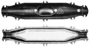
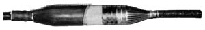
Table 2.
| Type of |
Lead |
Cross-section |
Dimensions
ca. mm |
Weight
ca. kg |
| joint box |
sleeve |
(mm2) |
l1 |
l2 |
l3 |
d1 |
d2 |
h |
b |
Cast
iron box |
Lead
sleeve |
Compound
VUM |
Compound
SP |
| KS 1150/H |
KSU 820 |
16-150 (15kV) |
1150 |
960 |
820 |
90 |
144 |
220 |
248 |
39 |
16,5 |
10 |
10 |
| KS 1350/H |
KSU 950 |
185-240 (15 kV) 16-150 (20 kV) |
1350 |
1100 |
950 |
105 |
158 |
250 |
280 |
68 |
20 |
13,5 |
14 |
| KS 1640/H |
KSU 1170 |
185-240 (20 kV) 35-240 (35 kV) |
1640 |
1320 |
1170 |
120 |
178 |
300 |
326 |
94 |
28,5 |
20 |
31 |
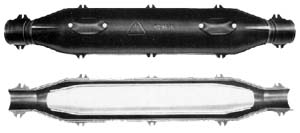
Table 3.
| Type of |
Lead |
Cross-section |
Dimensions
ca. mm |
Weight
ca. kg |
| joint box |
sleeve |
(mm2) |
l1 |
l2 |
l3 |
d1 |
d2 |
h |
b |
Cast
iron box |
Lead
sleeve |
Compound
VUM |
Compound
SP |
| KS 1150/HE |
KSU 470 |
16-150 (15kV) |
1150 |
960 |
470 |
90 |
68 |
220 |
248 |
39 |
11 |
3 |
17 |
| KS 1350/HE |
KSU 580 |
185-240 (15 kV) 16-150 (20 kV) |
1350 |
1100 |
580 |
105 |
76 |
250 |
280 |
68 |
15 |
5 |
24 |
| KS 1640/HE |
KSU 750 |
185-240 (20 kV) 35-240 (35 kV) |
1640 |
1320 |
750 |
120 |
90 |
300 |
326 |
94 |
22,5 |
8 |
41 |
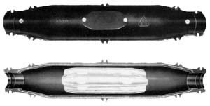
Table 4.
| Type of |
Lead |
Cross-section |
Dimensions
ca. mm |
Weight
ca. kg |
| joint box |
sleeve |
(mm2) |
l1 |
l2 |
l3 |
d1 |
d2 |
h |
b |
Cast
iron box |
Lead
sleeve |
Compound
VUM |
Compound
SP |
| KS 1640/P |
KSU 1070 |
25-240 (20 kV) 35-240 (35 kV) |
1640 |
1320 |
1070 |
120 |
178 |
300 |
326 |
94 |
27 |
19 |
30 |

Table 5.
| Type of |
Lead |
Cross-section (mm2) |
Dimensions
ca. mm |
Weight ca.
kg |
| joint box |
sleeve |
single
core
1 kV |
two
cores
1 kV |
three
cores
1, 6 and
10 kV |
four cores
1-10 kV |
l1 (L) |
l2 |
l3 |
d1 |
d2 |
h |
Sleeve |
Filling
compo-und |
| |
|
|
|
35-50 (1) |
|
|
|
|
|
|
|
|
|
| KSR 26 |
KSRU 26 |
do 185 |
do 50 |
6-25 (6) |
do 25 |
570 |
462 |
362 |
231 |
37 |
126 |
11 |
5 |
| |
|
|
|
10 (10) |
|
|
|
|
|
|
|
|
|
| |
|
|
|
70-120 (1) |
|
|
|
|
|
|
|
|
|
| KSR 34 |
KSRU 34 |
240-400 |
70-95 |
35-70 (6) |
35-50 |
680 |
558 |
434 |
280 |
45 |
160 |
18 |
7 |
| |
|
|
|
25-50 (10) |
|
|
|
|
|
|
|
|
|
| |
|
|
|
150-185 (1) |
|
|
|
|
|
|
|
|
|
| KSR 43 |
KSRU 43 |
500-630 |
120-150 |
95-120 (6) |
70-95 |
780 |
640 |
492 |
320 |
54 |
177 |
24,5 |
10 |
| |
|
|
|
70-120 (10) |
|
|
|
|
|
|
|
|
|
| |
|
|
|
240-300 (1) |
|
|
|
|
|
|
|
|
|
| KSR 53 |
KSRU 53 |
800-1000 |
185-240 |
150-240 (6) |
120-150 |
880 |
720 |
557 |
360 |
64 |
203 |
38 |
16 |
| |
|
|
|
150-185 (10) |
|
|
|
|
|
|
|
|
|
| |
|
|
|
400 (1) |
|
|
|
|
|
|
|
|
|
| KSR 64 |
KSRU 64 |
- |
300 |
300-400 (6) |
300 |
1100 |
824 |
692 |
462 |
75 |
254 |
44,5 |
30 |
| |
|
|
|
240-300 (10) |
|
|
|
|
|
|
|
|
|
    
|