PREFACE
There are two types of feed for lighting
fixtures located along a runway - parallel or series feed. As a circuits of a runway are
several kilometers long with the parallel feed, a progressive voltage drop occurs from one
light to the other, even with wide cable ' sections. This results in expensive cable and a
heterogeneous luminous intensity of lights. Additionally, low-voltage prefocus lamps still
require a step-down transtormer.
A series feed requires the utilization of a constant current regulator, isolating
transformers and lamps specially designed for rated current of 6.6 A or 20 A. All lighting
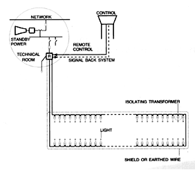
fixtures are now designed for use these lamps. Figure 1 shows an alternate feed of runway
lights by series circuits.

Sl.1
The regulator is connected to a
conventional monophase supply with a disconnector and fuses. The supply is provided by the
electricity network or standby generator set.
The series circuit, which is thus known as the primary circuit, consists of a
single-conductor cable connecting in series the light isolating transformers.
The transformers have a salient features:
- protect personnel by insulating the high voltage primary circuit from the secondary supplying light,
- high reliability thanks to systematic tests at all manufacturing stages,
- self-protected: operates indefinitely at full load, in short-circuit or in open circuit, at ambient temperatures ranging between -55°C and +65°C,
- the cables are an integral part of the transformer ensuring perfect watertightness,
- The coating is acid-, alkali-, and oil-resisting and also resists other chemical agents, as well as ozone and U.V. May be immersed, buried or exposed to the sun and to bad weather,
- maintaining the continuity of the primary circuit when the light is out of service
- simple and quick repairs through the easy disconnection of the doubtful cable sections
- operates either at 50 Hz or 60 Hz on series circuits rated up to 5000 V.
The secondary of each isolating transformer is normally connected to a single light by means of a secondary two-core cable or 2 single-core cables; but it possible to connect several lights when they are close to one another with a single transformer secondary. This arrangement, which is sometimes more economical, should be used with discrimination, for results in the use of more powerful transformers giving, in open circuit, a higher voltage, which may be dangerous for maintenance personnel.

Sl. 2
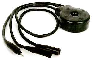
The transformer is completely moulded in a layer of high
standard elastomere which covers the two primary single-core primary cables and the
secondary two-core cable. Toroidal magnetic core made of low-loss, grain-oriented
laminations, insulated by a nylon sheath.
The transformer complies with the FAA specification AC 150/534547.
The primary leads, one which ends with a factory moulded singlepole plug, FAA L-823, Style
2 and the other with a factory moulded single-pole receptacle, FAA L-823, Style 9.
The secondary lead, which incorporates a factory moulded twopole receptacle, FAA L-823,
Style 7.

Sl 3.
The isolating transformers include segments of primary
and secondary cables equipped with sealed impervious connectors. They can be buried near
the light but it is preferable for them to be housed in an inspection man-hole such as the
one in Fig. 3.
The primary cable is connected in segments from one transformer to another. It is buried
in a trench joining the inspection manholes, between two layers of sand, out of reach of
stones or any objects which could damage it.
The 3 or 5 kV insulation cable may or may not incorporate a concentric shield.
An unshielded cable will generally have to be protected from the effects of the weather by
means of a bare equipotentional earth wire located about 10 cm, above it in the trench.
The shield and equpotentional wire are connected with the regulator ear connection. On
cables with a shield, the shield is insulated by the protective sheath, and should be
connected with earth rods about every 300 m. The secondary cable connects the light to the
transformer by means of a moulded plug or a KIT model to be mounted on the spot. This
connection, running along a trench, in a wireway in the pavement or in a tube, can be made
by means of a two-core cable or two segments of single-core cable joined, on the
transformer side, to a KIT plug, Style 4. These secondary equipment are 1 kV isolated but
the practical utilization voltages scarcely exceed 135 V.
The isolating transformer shall be in full
compliance with FAA L830 and L-831 specification (AC 150/5345-47).
The magnetic core shall be of toroidal shape, made from very low-loss, grain oriented
steel laminations. Primary and secondary windings may not be superimposed to each other
but shall be adequately separated.
The synthetic rubber encapsulation shall be made under pressure over transformer and
connection leads. The main characteristics shall be 'equal to or better those given in
table below.
MAIN CHARACTERISTICS
| Specification FAA |
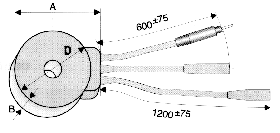
Nominal characteristics | Nominal characteristics | Max. output voltage at open circuit* | Dimensions u mm (Sl.2) | ||||||||||||||||||||||
| Rated wattage | Curents | Load | Minimum efficiency | Min. power factor | ||||||||||||||||||||||
| 60 Hz | 50Hz | Primary | Secondary | Ohm | Max. | |||||||||||||||||||||
| W | A | A | Ohm | W | % | RMSV | A | B | D | |||||||||||||||||
| L-830-1 | L-831-1 | 30/45 | 6,6 | 6,6 | 1,15 | 50 | 80 | 0,95 | 25 | 180 | 58 | 140 | ||||||||||||||
| L-830-4 | L-831-4 | 100 | 6,6 | 6,6 | 2,44 | 106 | 85 | 0,95 | 70 | 200 | 74 | 150 | ||||||||||||||
| L-830-5 | L-831-5 | 150 | 6,6 | 6,6 | 3,67 | 160 | 90 | 0,95 | 80 | 220 | 77 | 175 | ||||||||||||||
| L-830-6 | L-831-6 | 200 | 6,6 | 6,6 | 4,82 | 210 | 90 | 0,95 | 100 | 220 | 77 | 175 | ||||||||||||||
* Values for primary winding supplied by sine-wave voltage at nominal current.