Connectors for printed circuit boards
Printed Circuit Connectors
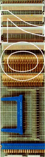
PRINTED CIRCUIT CONNECTORSGRUP 1
Application
Printed circuid connectorst series 07 Group 1 are foreseen for the application in telecomm unication and electronic units for frame or panel mounting by means of nuts or guides.
They are applied for direkt connection of printed boards and electric wiring with other unit and sistem components.
They are manufactured with 3,96 and 4 mm spacing and contact number 6,12,18 and 22 and printed boards 1,6mm thick.
By using of a special plug 3,96 mm spacing fixed with nuts to printed board connectors with the equal spacing can be independent from printed board thickness.
Connectors of this series fully meet all standard requirements.
Insulator
Made of diallylphaltate (3,96 mm spacing) or macrolon ( 4 mmspacing).
Polarization
With insertion of a polarization key at any contact point it is oossible with the loss of such contact to perform connector polarization.
Contacts
Contacts are golr-plated special bronze.
Connection terminations of conductor are for jointing by soldering.Max. current as per contact
is 5 A.
Klimate class
40/085/21
Service life
1000 mating and unmating cycles.
ELECTRICAL CHARACTERISTICS
| Max.
operating voltage (Veff) |
ITesting voltage |
Insulantion
resistance |
Contact resistence |
|
Prior to climate testing |
After climate testing |
|||
500 |
1500 |
>= 105 | > 103 |
< 5 |
GROUP 2
Aplication
Printed circuit connectors Series 07, Group 2 are applied for direct connection of printed boards and their electric conductod wiring with other unit conponents.
Thy are foreseen for board mounting with clamps.
Thy are manufacture with 5 and 7 contacts with 4mm spacing.Nominal printed board thickness for these connectors is 1,6mm.
Insulator
Made of polyamide in natural colour.
Polarization
Polarization 7-pole connector is provided by construction of insulating body by means of a comparment being between contact No. 3 and 4 Polarization at 5-pole connector is performed with insertion of polarization key into socket of any contact. In such way number of contacts is reduced to 4.
Contacts
Contacts are made of special bronze, hard gold plated over nickel layr.
Klimate class
40/085/21
Service life
1000 mating and unmating cicles.
ELECTRICAL CHARACTERISTICS
| Max.operating | Max. current |
Testing |
Insulation |
Contact |
voltage |
as per contact |
voltage |
resistance |
resistsnce |
(Veff) |
(A) |
(Veff) |
(Ohm) |
(mOhm) |
500 |
5 |
1500 |
> 109 |
< 5 |
GROUP 3
Application
Printed circuit connectors Series 07, Group 3 are applied for direct printed board connection and their electric conductor wiring with other unit components.They are foreseen for board mouting by screw M3. They are manufactured with 15 and 22 contacts and 3,96mm (0,156") spacing.
Nominal printed board thickness for these conectors is 16mm.
Guides provide proper guiding of printed boars.
Insulator
Made of dialylphtalete.
Polarization
Printed board polarization is possible with insertion of polarization key into edge socket of any contact.In this way number of operating contacts is reduced.
Contacts
Made of hard gold plated special bronze.Under this protective cover a nickel layer can be plated.Conductor connection terminations are for jointing by soldering .
Climate class
40/085/21
Service life
1000 mating and unmating cycles.
ELECTRICAL CHARACTERISTICS
| Max.operating | Max. current |
Testing |
Insulation |
Contact |
voltage |
as per contact |
voltage |
resistence |
resistence |
(Veff) |
(A) |
(Veff) |
(Ohm) |
(mOhm) |
500 |
5 |
1500 |
> 109 |
< 5 |
GROUP 4
Application
Accessories used for printed circuit connectors serve for a wider and easier application where is necessary to set on a determined space several connectors and to provide inerrelation of all elements as required.
For that purpose the following acessories ane used:
Guide
Distancer
Clamp
Contact rail
Accessories are used with connectors Series 07-1.
The mounting scheme of quides and clamps on supporting rails is shown on the riqure below.
PRINTED BOARD PINS SPACING 3,96 mm
GROUP 5
Application
Printet Board Pins are applied for indirect connection of printed boards in receptacles 3,96 mm spacing
They are fixed to printed board with 2 nuts M3, type and necessary length.
Insulating Body
Made of diallylphtalat.
Contacts
Copper alloy hard gold plated.
Polarization
If polarization of printed board is wanted, contact must be removed at point where polarization fuse is set in receptacle.
Climate class
40/085/21
Service life
1000 mating and unmating cycles
ELECTRICAL CHARACTERISTICS
| Max. operating volage | Testing voltage |
Insulation
resistence |
Contact max. resistence |
Max. current |
|
(Veff) |
(Veff) |
||||
before climate test |
after climate |
||||
500 |
1500 |
> 105 | > 105 | < 5 | 5 |
GROUP 6
These connectors are applied for calculators, TV sets and similar electronic devices fod direct connection of printed boards - modules, 50 or 100 mm wide, nominal thickness, spacing 2,54mm with soldering connections.Contacts are made of copper alloy , tinned or untinned coating.
Insulating body of polycarbonate in natural colour.
Connector mounting is performed in panel mounting hole by insulating body ins and fixing by soldering of contacts to board.
Polarization is carried out with fixing the polarization insert. Prevention of accidental switching off printed board is achieved by fuse.
Technical data
Nominal current at ambient temperature:
4A max.
2A at 600 C
1A at 900 C
Nominal voltage: 250 V
Contact ressistance: 10 mOhm max
Dielectric strength: 2000 V
Insulation resistance: 1014 Ohm
Operating temperature: -40 0C up to 125 0C
Pull-out force: 9 pole - 20N
19 pole - 40N
Service life: 50 cycles
Printed circuit BOARD connectors SPACING 2,54 mm
GROUP 7
Application
Printed circuit board connectors Series 07, Group 7 are applied in telecommunication units and Systems s.c. ISEP construction for interwiring of unit components throgh printed board with direct and indirect connections.
For indirect connection of printed board are used male contact connectors with terminations for solder jointing C type and single - row pins (S and F type) or double row (A, M , D tupe). (Pin connectors A and M are for jointing with printed board in 2 rouws chess arrgement). Pins M type are opposite arranged from pins A type. D type arrangement is in 2 parallel rows but with double number of contacts ( only with 2x33=66 contacts). A,D, M, and S type arrangements are for jointing through printed board and F type for soldering on printed board.
All connectors with male contacts are fixsid to printed board with rivets and nuts.
Connectors with socket contacts are applied for mounting to unit by a clamp (A type) or, using special metal holders with fixing holes (B type).
They are foreseen for mating with contsct on printed boart or printed board contact part nominal thickness 1,6 mm. Contact terminations for wiring connection are for jointing by wrapping or soldering holes.
Connectors of this series are made with spscing 2,54 mm and 11, 25, and 33 contacts.These connectors meet JUS N.R4.111 , IEC - 130 - 11, DIN 41620 requirements under CANNON licence.
Insulating body
Insulating body with socket contacts is made of polycarbonate with glass filler.
Contacts
Socket contacts are of special bronze with termination for wiring by wrapping or soldering.
Pin contacts are of brass and terminations for jointing to printed board by soldering. Both contact types are gold plated and reinforced gold plate on contact surfaces.
Climate class
40/125/21
Service life
600 mating cycles
ELECTRICAL CHARACTERISTICS
Operating voltage |
Current per contact |
Testing voltage |
Insulation resistence |
Contact resistente |
(Veft) |
(A) |
(Veff) |
(Ohm) |
(mOhm) |
250 |
5 |
750 |
> 10 12 | < 10 |